Preparing the POP Kiosk Hardware
Overview
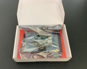
During the initial prototyping and evaluation of this project, we prepared each kiosk’s electronics ahead of time, while only printing the kiosk cases as needed. Once completely constructed, the kiosk’s electronics can be stored safely in the touchscreen’s box. In this section, we will detail how to prepare the electronics.
Prepare the Touchscreen
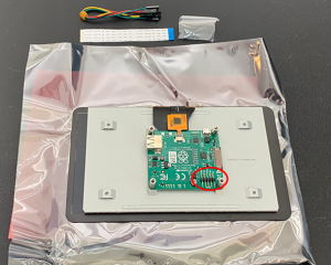
Remove the touchscreen from the box and place on the protective foam, on top of the gray electrostatic discharge bag. We recommend that you keep the film screen protector on the display to prevent scratching. Remove all additional parts from the box before setting it aside. Place the touchscreen display so that the ribbon cable connecting the display to the controller board is facing away from you. This will place the five pins circled in red on the bottom right of the controller board, facing towards you.
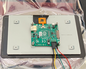
First, we will be installing the four color-coded cables that are provided with the touchscreen. These are used by the display to receive power and touch input data from the Raspberry Pi computer. We will start by connecting them to the proper pins on the display’s circuit board. These power cables are connected to the five pins on the lower right corner.
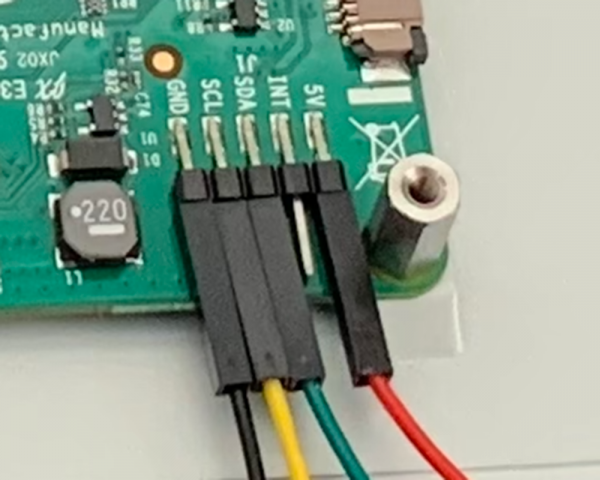
There are five pins, but there are only four cables. This is because, starting from the right side, we will be skipping the second pin. We will be connecting the red cable to the pin labeled “5V”, which will be used to power the display. The green cable connects to the pin labeled “SDA”, which is used to transmit touch input data. The yellow cable connects to the pin labeled “SCL”, which is used to keep the display and computer in sync. Finally, the black cable will connect to the pin labeled “GND”, which will act as the ground.
Prepare the Raspberry Pi
Now that we have the touchscreen prepared, we can start to focus on getting the Raspberry Pi mounted. The display comes with four stand-off screws pre-installed, which we can use to attach our Raspberry Pi. Before we do that, however, we should install the heatsinks to our Raspberry Pi. They can be purchased separately or as part of a Raspberry Pi bundle, through resellers like Canakit or Adafruit.
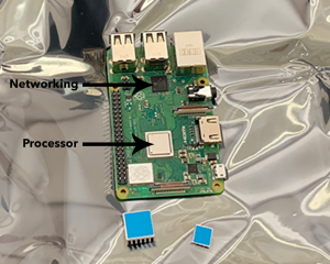
Each heatsink has small adhesive pads on its backside that can be used to attach it directly to the Raspberry Pi computer. We have two heatsinks that we will use for the primary processor and the networking chip. To apply them, simply remove the protective backing on the adhesive and place directly on the chip.
The larger heatsink will be applied to the primary processor, which is the polished metal chip in the center of the board. Do not place the heatsink on the metal chip with the Raspberry Pi logo on it, because covering it can decrease wireless network connectivity. The second smaller heatsink is placed on the networking chip, which is located near the USB ports.
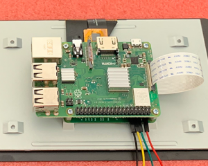
Once the heatsinks are installed, we can now mount the Raspberry Pi computer onto the touchscreen. Place the Raspberry Pi on top of the touchscreen controller board so that the holes on the Raspberry Pi board line up with the four stand-off screws. Position the Raspberry Pi so that the DSI port is on the same side as the ribbon cable that is sticking out of the touchscreen controller board. Use the four provided screws to attach the Raspberry Pi.
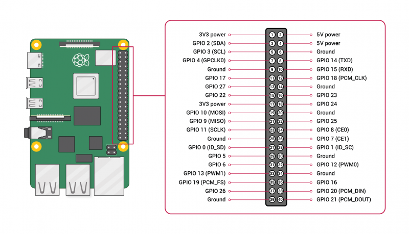
The final step will be connecting the four color-coded pins to the Raspberry Pi GPIO 30-pin port, which can be found along the long side of the computer.
We will be connecting the same pins on the touchscreen controller and Raspberry Pi GPIO port. The red “5V” cable can be connected to pin 4 (“5V power”), and will provide power to the display. The green “SDA” cable can be connected to pin 3 (“GPIO 2 SDA”), and will transmit touch input data. The yellow “SCL” cable can be connected to pin 5 (“GPIO 3 SCL”), and will keep the computer and display in sync. The black “GND” cable will connect to pin 6 (“Ground”), and will act as the ground.
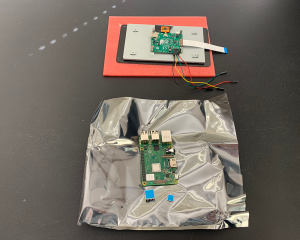
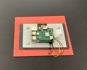
After the cables are all connected, you can place the entire construction into the gray electrostatic discharge bag. Using the protective foam on the bottom of the touchscreen display box, you can safely store the electronics until they are needed to construct a kiosk.
