Difference between revisions of "Assembling the POP Kiosk Case"
| (10 intermediate revisions by the same user not shown) | |||
| Line 21: | Line 21: | ||
=== Protecting the Parts === | === Protecting the Parts === | ||
The final surface of the printed part can be sealed using a clear coat spray paint to change the surface finish and provide some minor abrasion protection to the paint. For increased durability, you can use a two-part clear epoxy resin that needs to be mixed before application. These epoxy resin come in different consistencies, creating a very different application process for each. Epoxy resins designed for 3D printed parts are | The final surface of the printed part can be sealed using a clear coat spray paint to change the surface finish and provide some minor abrasion protection to the paint. For increased durability, you can use a two-part clear epoxy resin that needs to be mixed before application. These epoxy resin come in different consistencies, creating a very different application process for each. Epoxy resins designed for 3D printed parts are thinner and easier to apply to parts with more complex geometries. These coatings are best applied with a foam brush. | ||
==Securing Hardware== | ==Securing Hardware== | ||
| Line 27: | Line 27: | ||
=== Installing the Mount System Hex Nuts === | === Installing the Mount System Hex Nuts === | ||
Once the case is finished, you can install the six M5 hex nuts that are used to secure the Modular Mounting Adapter. Inside the case, there are six slots for these M5 hex nuts to snap into place. | Once the case is finished, you can install the six M5 hex nuts that are used to secure the Modular Mounting Adapter. Inside the case, there are six slots for these M5 hex nuts to snap into place. | ||
[[File:Modular Mount Screw Locations.png|alt=Modular Mount Screw Locations|none|thumb|Modular Mount Screw Locations]] | |||
Depending on printing tolerances and anomalies, you may need to trim these slots or use moderate force to get them into place. We recommend using hot glue to hold these nuts in place for added stability. Super glue has a stronger hold, but can make it difficult to remove these hex nuts later for recycling. | Depending on printing tolerances and anomalies, you may need to trim these slots or use moderate force to get them into place. We recommend using hot glue to hold these nuts in place for added stability. Super glue has a stronger hold, but can make it difficult to remove these hex nuts later for recycling. | ||
=== Installing the VESA Mount Hex Nuts === | === Installing the VESA Mount Hex Nuts === | ||
To use the POP Kiosk with the 75mm by 75mm VESA mount, you will need to mount to the four M4 nuts. Similar to the Mounting System Adapter, these nuts have four slots that can be used to hold these nuts in place. We also recommend using hot glue to anchor these nuts in place. | To use the POP Kiosk with the 75mm by 75mm VESA mount, you will need to mount to the four M4 nuts. Similar to the Mounting System Adapter, these nuts have four slots that can be used to hold these nuts in place. We also recommend using hot glue to anchor these nuts in place. | ||
[[File:VESA Screw Locations.png|alt=VESA Screw Locations|none|thumb|VESA Screw Locations]] | |||
===Installing Dust Screens=== | ===Installing Dust Screens=== | ||
We recommend installing fiberglass or similar mesh inside of the kiosk case, covering the ventilation holes. | We recommend installing fiberglass or similar mesh inside of the kiosk case, covering the ventilation holes. Covering all of the ventilation points can help decrease the dust and dirt accumulating inside the kiosk and clogging the cooling fan. Only the mesh shown below is required. The adhesive on the screen repair tape allows the mesh to quickly adhere to the case. We recommend cutting the mesh a little larger than needing and hot gluing this excess to the inside of the case, as well. | ||
[[File:Fan Mesh Location.png|alt=Fan Mesh Location|none|thumb|Fan Mesh Location]] | |||
===Installing the 30mm Fan=== | ===Installing the 30mm Fan=== | ||
The 30mm x 30mm fan can be installed inside of the POP kiosk case using the four M2.5x10mm machine screws and four M2.5 hex nuts. We recommend installing the machine screws with the cap on the outside of the case and the nuts inside the case. The fan should be installed on top of the fiberglass mesh screen so that the mesh is in between the fan and case. | The 30mm x 30mm fan can be installed inside of the POP kiosk case using the four M2.5x10mm machine screws and four M2.5 hex nuts. We recommend installing the machine screws with the cap on the outside of the case and the nuts inside the case. This may require using an thin blade or screwdriver to poke a hole in the mesh so the screw can be pushed through. The fan should be installed on top of the fiberglass mesh screen so that the mesh is sandwiched in between the fan and case. | ||
[[File:Fan Mount Location.png|alt=Fan Mount Location|none|thumb|Fan Mount Location]] | |||
===Installing the USB-C Panel Mount=== | ===Installing the USB-C Panel Mount=== | ||
The USB-C Panel Mount can be installed inside of the case using the two M3x10mm machine screws. Thread the screws through the kiosk case holes and line up the panel mount cable inside the case, using a hex wrench to tighten both sides slowly and equally. | The USB-C Panel Mount can be installed inside of the case using the two M3x10mm machine screws. Thread the screws through the kiosk case holes and line up the panel mount cable inside the case, using a hex wrench to tighten both sides slowly and equally. | ||
[[File:Panel Mount Location.png|alt=Panel Mount Location|none|thumb|Panel Mount Location]] | |||
===Attaching the Maintenance Panel=== | ===Attaching the Maintenance Panel=== | ||
The maintenance panel can be attached to the kiosk case using one M2x6mm machine screw. We recommend installing the machine screws with the cap on the outside of the case. | The maintenance panel can be attached to the kiosk case using one M2x6mm machine screw. We recommend installing the machine screws with the cap on the outside of the case. | ||
[[File:Maintenance Panel Screw Location.png|alt=Maintenance Panel Screw Location|none|thumb|Maintenance Panel Screw Location]] | |||
== Installing Electronics == | == Installing Electronics == | ||
=== Attaching the USB-C Panel Mount === | === Attaching the USB-C Panel Mount === | ||
Finally, we can attach the USB-C cable from the panel mount to the USB-C power port on the Raspberry Pi. This cable acts as a power passthrough, allowing us to quickly remove the power cable from the kiosk without putting repetitive strain on the Raspberry Pi computer board itself. | |||
[[File:Raspberry Pi 4 USB-C Location.png|alt=Raspberry Pi 4 USB-C Location|none|thumb|Raspberry Pi 4 USB-C Location]] | |||
The USB-C end of the panel mount is at a right angle and the wire should point towards the end of the Raspberry Pi computer with ethernet and USB ports. Once attached, this wire can be coiled once then placed between the Touchscreen Controller board and the Raspberry Pi computer. | |||
=== Wiring the 30mm fan === | |||
Now that all of the hardware is installed inside the kiosk case, we can wire the 30mm fan. The two fan wires (the red 5V and the black Ground) need to be attached to the GPIO port, which is the strip of pins along the side of the Raspberry Pi computer. | |||
[[File:Raspberry Pi 4 GPIO Location.png|alt=Raspberry Pi 4 GPIO Location|none|thumb|Raspberry Pi 4 GPIO Location]] | |||
Based on the diagram below, we need to plug the red 5V wire into the 5V pin, located at either pin 1 or pin 2. We also need to plug the black Ground wire into the Ground pin, which is located at pin 6. | |||
[[File:Raspberry Pi GPIO Port.png|alt=Raspberry Pi GPIO Port|none|thumb|Raspberry Pi GPIO Port]]Depending on the length of the fan wires, you may be required to prop the kiosk case at an angle to attach these two wires before closing the case. Once these two wires are attached, you can take the case and enclose the kiosk electronics. It may take some wiggling and re-positioning of wires to get the case to close fully. | |||
=== Mounting the Kiosk Electronics === | === Mounting the Kiosk Electronics === | ||
Once the kiosk electronics are inside of the case, the last step is to use the four M3x10mm machine screws to attach the kiosk case to the mounting brackets on the Official 7" Raspberry Pi Touchscreen. Be sure not to overtighten these screws because it is possible to damage the touchscreen display module. | |||
[[File:Display Mount Screw Locations.png|alt=Display Mount Screw Locations|none|thumb|Display Mount Screw Locations]] | |||
== Finishing the Kiosk == | == Finishing the Kiosk == | ||
=== Attaching Modular | === Attaching Modular Accessories === | ||
{{ | [[File:Kiosk with Foot Attached.png|alt=Kiosk with Foot Attached|none|thumb|Kiosk with Foot Attached]] | ||
Once the display is secured to the case, you can attach accessories such as a collar, bumper, cover, or the Modular Mounting System adapter. Thumbscrews can be used to quickly remove accessories for storage or swap them out as the need arises. | |||
{{See|Printing the POP Kiosk Case}} | |||
=== Power on The Kiosk === | === Power on The Kiosk === | ||
The kiosk will automatically turn on once the USB C power cable is plugged in. If you are using the CLIO Quick Start image, then you will see the POP logo while the CLIO web interface loads. The kiosk can be turned off manually through the CLIO Facilitator Mode interface, under the Settings menu. An optional PiSwitch from CanaKit allows you to turn the kiosk on and off without unplugging the cable. | |||
==Updating the Kiosk== | ==Updating the Kiosk== | ||
After we have our kiosk up and running, we can begin to update the content we display on the kiosk. This can be done through a USB flash drive on the kiosk itself, or through SSH after internet connectivity has been enabled.{{See|Updating the POP Kiosk}}{{DocumentationNavigation}} | After we have our kiosk up and running, we can begin to update the content we display on the kiosk. This can be done through a USB flash drive on the kiosk itself, or through SSH after internet connectivity has been enabled.{{See|Updating the POP Kiosk}}{{DocumentationNavigation}} | ||
Latest revision as of 16:44, 10 March 2023
Refining the Print
After the parts are printed and removed from the bed, there's still a few steps to go before you have a final kiosk.
This process creates a fine dust of harmful microplastic particulates and involves chemicals that produce noxious fumes. You should always wear protective goggles, a mask, gloves and wash your clothes after sanding is finished. Always ensure you have adequate ventilation.
Removing Excess Supports
When creating objects with many forms of 3D printing, you will need to remove the excess material the print uses to create support structures. The POP kiosk case is the only print that requires extensive support structures and we recommend the Cura Slicer program's "Tree Supports" option for ease of removal.
These supports are made to be removed and the process is generally straight forward. Using a pair of side-cutting pliers, you can cut any support connections. Then, use needle-nose pliers to remove the support structures.
Filling and Sanding the Parts
After the support structures are removed, there may be some marks left on the final part's surface. These can generally be removed by using sandpaper. Start with 120-grit sandpaper and progressively work your way up to 1500-grit sandpaper.
Working in a straight line with low-grit paper can quickly remove marks from the printed surface, while sanding in tight circles with higher-grit paper can help minimize the appearance of surface anomalies. During this sanding process, you can use a spot putty to fill large gouges or soften layer lines. When using 1000-grit or higher sandpaper, you can incorporate water into the process to increase the surface polish.
Painting the Parts
Before you can use spray paint on a finished print, it is generally recommended to use a primer. Some spray paint includes a primer for a one-step painting process. Hang or mount the part in a way that allows you to cover the entire surface without needing to handle the part. Use wide strokes that pass over the part being painted, but do not start or stop on it. Always try to hold the spray paint can nozzle 10" - 12" from the object. Use multiple thin layers to improve evenness and decrease paint running. It is important to let the part dry completely without handling for at least 24 hours.
Protecting the Parts
The final surface of the printed part can be sealed using a clear coat spray paint to change the surface finish and provide some minor abrasion protection to the paint. For increased durability, you can use a two-part clear epoxy resin that needs to be mixed before application. These epoxy resin come in different consistencies, creating a very different application process for each. Epoxy resins designed for 3D printed parts are thinner and easier to apply to parts with more complex geometries. These coatings are best applied with a foam brush.
Securing Hardware
Installing the Mount System Hex Nuts
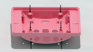
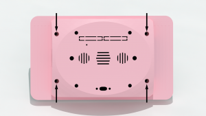
Once the case is finished, you can install the six M5 hex nuts that are used to secure the Modular Mounting Adapter. Inside the case, there are six slots for these M5 hex nuts to snap into place.
Depending on printing tolerances and anomalies, you may need to trim these slots or use moderate force to get them into place. We recommend using hot glue to hold these nuts in place for added stability. Super glue has a stronger hold, but can make it difficult to remove these hex nuts later for recycling.
Installing the VESA Mount Hex Nuts
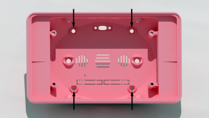
To use the POP Kiosk with the 75mm by 75mm VESA mount, you will need to mount to the four M4 nuts. Similar to the Mounting System Adapter, these nuts have four slots that can be used to hold these nuts in place. We also recommend using hot glue to anchor these nuts in place.
Installing Dust Screens
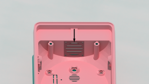
We recommend installing fiberglass or similar mesh inside of the kiosk case, covering the ventilation holes. Covering all of the ventilation points can help decrease the dust and dirt accumulating inside the kiosk and clogging the cooling fan. Only the mesh shown below is required. The adhesive on the screen repair tape allows the mesh to quickly adhere to the case. We recommend cutting the mesh a little larger than needing and hot gluing this excess to the inside of the case, as well.
Installing the 30mm Fan
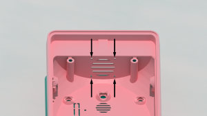
The 30mm x 30mm fan can be installed inside of the POP kiosk case using the four M2.5x10mm machine screws and four M2.5 hex nuts. We recommend installing the machine screws with the cap on the outside of the case and the nuts inside the case. This may require using an thin blade or screwdriver to poke a hole in the mesh so the screw can be pushed through. The fan should be installed on top of the fiberglass mesh screen so that the mesh is sandwiched in between the fan and case.
Installing the USB-C Panel Mount
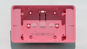
The USB-C Panel Mount can be installed inside of the case using the two M3x10mm machine screws. Thread the screws through the kiosk case holes and line up the panel mount cable inside the case, using a hex wrench to tighten both sides slowly and equally.
Attaching the Maintenance Panel
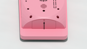
The maintenance panel can be attached to the kiosk case using one M2x6mm machine screw. We recommend installing the machine screws with the cap on the outside of the case.
Installing Electronics
Attaching the USB-C Panel Mount
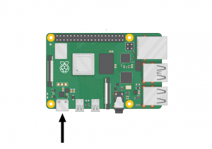
Finally, we can attach the USB-C cable from the panel mount to the USB-C power port on the Raspberry Pi. This cable acts as a power passthrough, allowing us to quickly remove the power cable from the kiosk without putting repetitive strain on the Raspberry Pi computer board itself.
The USB-C end of the panel mount is at a right angle and the wire should point towards the end of the Raspberry Pi computer with ethernet and USB ports. Once attached, this wire can be coiled once then placed between the Touchscreen Controller board and the Raspberry Pi computer.
Wiring the 30mm fan
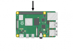
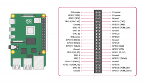
Now that all of the hardware is installed inside the kiosk case, we can wire the 30mm fan. The two fan wires (the red 5V and the black Ground) need to be attached to the GPIO port, which is the strip of pins along the side of the Raspberry Pi computer.
Based on the diagram below, we need to plug the red 5V wire into the 5V pin, located at either pin 1 or pin 2. We also need to plug the black Ground wire into the Ground pin, which is located at pin 6.
Depending on the length of the fan wires, you may be required to prop the kiosk case at an angle to attach these two wires before closing the case. Once these two wires are attached, you can take the case and enclose the kiosk electronics. It may take some wiggling and re-positioning of wires to get the case to close fully.
Mounting the Kiosk Electronics
Once the kiosk electronics are inside of the case, the last step is to use the four M3x10mm machine screws to attach the kiosk case to the mounting brackets on the Official 7" Raspberry Pi Touchscreen. Be sure not to overtighten these screws because it is possible to damage the touchscreen display module.
Finishing the Kiosk
Attaching Modular Accessories
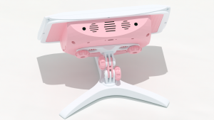
Once the display is secured to the case, you can attach accessories such as a collar, bumper, cover, or the Modular Mounting System adapter. Thumbscrews can be used to quickly remove accessories for storage or swap them out as the need arises.
Power on The Kiosk
The kiosk will automatically turn on once the USB C power cable is plugged in. If you are using the CLIO Quick Start image, then you will see the POP logo while the CLIO web interface loads. The kiosk can be turned off manually through the CLIO Facilitator Mode interface, under the Settings menu. An optional PiSwitch from CanaKit allows you to turn the kiosk on and off without unplugging the cable.
Updating the Kiosk
After we have our kiosk up and running, we can begin to update the content we display on the kiosk. This can be done through a USB flash drive on the kiosk itself, or through SSH after internet connectivity has been enabled.
| Documentation | |
|---|---|
| Installation | Look and Feel |
| Interaction Modes | Developing Activity Types |
| Creating an Interactive | Framework |
| Integrating CLIO | Contribute |
